Sunny Balasubramanian
Current quantitative researcher in the crypto & equities space. Formerly at Citadel, AQR, Columbia SEAS '16. Always cracking away at new (sometimes whimsical) problems using different kinds of technology. Please reach out to me at sunny.m.bala@gmail.com if you'd like to chat about any of my prior work or would like to hack on something together. LinkedIn | GitHub
Making Etch-a-Sketch Art With Python
by
The etch-a-sketch is one of the most frustrating drawing toys from childhood. Can we combine some code and motors to make this toy produce nice pictures? The answer is…
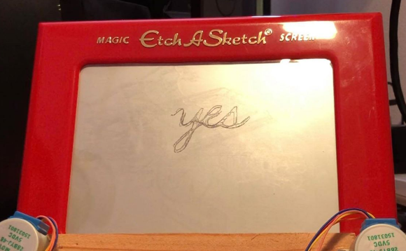
Sneak Peek at Finished Project
Background
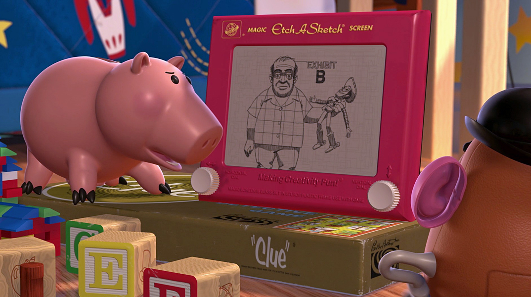
The Etch-A-Sketch was released by The Ohio Art Company in 1960. Ever since then, it’s been a staple toy in homes, daycares, waiting rooms and schools – over 100 million have been sold worldwide. It was even a big enough deal to be a character in Toy Story 1 and 2!
The popularity of the device is sort of interesting because it has lots of annoying problems:
- knobs only move the cursor up/down/left/right. Diagonals and curves require a steady precision that most children 3+ simply don’t have.
- you can’t draw two objects that are not connected.
- No ability to undo small mistakes. If you want to undo something you’ll have to redo your whole masterpiece.
The Plan
Write a program that uses some motors to draw nice pictures on an etch-a-sketch. For the reasons above, recreating pictures by hand is tedious and extremely difficult. My hope was to get to a point where my program could draw things better than I could. I’ve always wanted to learn more about how to use hardware with python so I was pretty excited to start this one.
Hardware Setup
Parts List Recipe:
- Raspberry Pi
- Etch a Sketch
- 1x Piece of Wood
- 2x Stepper Motor
- 2x Shaft Coupler
- 8x Jumper Cables
I’ve got the Amazon links above so it’s extra clear what I got – it seems like for these parts many of the manufacturers seem pretty similar, so I just picked the cheapest at the time.
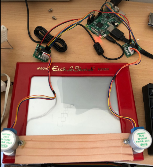
1. Hooking Up Motors to Raspberry Pi
Since the Raspberry Pi is just a tiny computer, we’re going to be able to use all the python libraries we know and love. Additionally, it has a set of GPIO pins to use. I connect a few of these pins to each of two controllers + motors. By changing the voltage on these pins, I can make motors to rotate. Here’s a link to the guide I followed to get this set up.
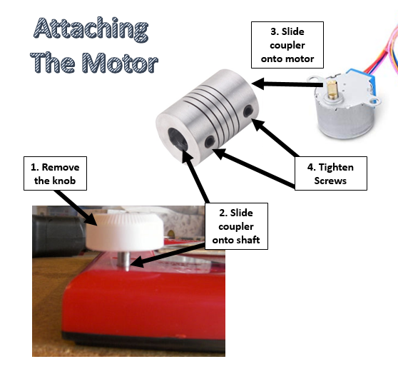
2. Connecting Motors to Knobs
With some force, the knobs can be removed from the etch-a-sketch. This reveals a shaft on the device. The motor also rotates a shaft, so to connect them together I used a chinese-finger-trap-like device called a coupler. It’s somewhat flexible, with two small sets of screws on either side that allow it to be tightened around each of the shafts. Here’s a mini-guide!
3. Stabilizing
There’s quite a bit of resistance on the etch a sketch knobs. Without doing anything, if we set the motor to rotate, the knob will actually stay still and the motor itself will rotate!
I went to a local hardware store with the dimensions of the build and they were able to cut me a block of wood that I could screw the motors into to keep them stable. I glued the wood on the bottom to the etch-a-sketch body. This can be tricky if the wood is not appropriately sized. With a screw too loose and the motor will wiggle around when it’s trying to rotate. If it’s too tight, the motor will be squeezed against the coupler and not be able to rotate.
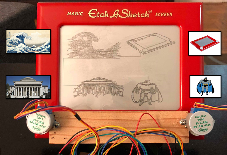
Final Build
Software Setup
There’s a few different ways to go about this portion of the project. When I started out, I googled to see if anyone had done things like this before. A few projects popped up. They seemed to approach the drawing in one of two ways. Some projects used the etch a sketch to draw in a grid and then “color” in the cells so that it looked like a picture. Other projects used toolpaths like the way 3D printers and metal cutting machines determine the routes they take. The advantage here is great paths, but creating the toolpaths is kind of a process.
I wanted to do it in a fully automated way where the only input is a picture and the output is a cleanly drawn image. The descriptions below will be mostly high level but all the code for this project is available on GitHub if you’d like to dive in at a deeper level.
1. Controlling Motors
The raspberry pi python library rpi lets us control the motor via the pins. I created a class to represent the motor, abstracting around the information from this guide I’ll be using this in the code is in the following way:
horizontalMotor = StepperMotor(horizontal_pins)
verticalMotor = StepperMotor(vertical_pins)

horizontalMotor.rotate(40)  # move cursor 40 units right
horizontalMotor.rotate(-40) # move cursor 40 units left
verticalMotor.rotate(40)  # move cursor 40 units up
verticalMotor.rotate(-40) # move cursor 40 units down
This is the core functionality we need. Now, as long as we know a path that we want to travel along, we can come up with a way to convert it to a series of instructions like above. For curves and diagonal lines, we can get the behavior we’re looking for by alternating instructions to the horizontal and vertical motors. For example, the code below will create a nice smooth diagonal line for us.
for step in range(40):
	horizontalMotor.rotate(1)
	verticalMotor.rotate(1)
2. Simplifying a Picture
I’m not going to kid myself about being able to create intricately detailed pictures using this etch-a-sketch. However, I do want a process that will take the original pictures and strip them down to the main details. We can do this using standard edge detection techniques like the Canny edge detector. Someone else has a great write-up on a pretty hands off approach to Canny edge detection in python.
That person’s code came in handy because the last thing I really wanted to be doing was trying to tune a bunch of different parameters. After all, the main point was to try to focus on the hardware! Below is an example of what you can expect from the edge detection.
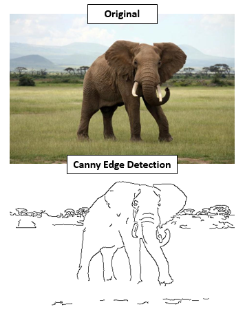
The results here play a big role in what I can / can’t draw. For example, landscapes, buildings, patterns and animals look a whole lot better than people. There’s a few more examples of this in result section below.
3. Picture to Instructions
This is a tricky step. A picture is just a collection of pixels. I’ll be finding a path here by converting my picture into a network/graph. Every pixel will become a node and every node will be connected to other nodes (pixels) within a 1 pixel radius.
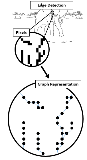
Some pictures will have many graphs and not all of them connect. For example, the grass/dirt at the bottom of the elephant picture. Since the etch-a-sketch can’t make jumps, I take the largest network that I can find. This gives me a simple picture that’s actually achievable on the etch-a-sketch.
Now that I have a single graph of points, I need to come up with what instructions to tell the motors. My strategy follows a standard depth first search approach. I’ll start at the leftmost point in the graph. From there, I’ll traverse nearby nodes, arbitrarily picking neighbors. If there are no neighbors at a given node, I backtrack to the last juncture and try a different route. My goal is to hit every node. I’m totally okay with retracing since the etch-a-sketch lines are pretty thin on first pass anyway.
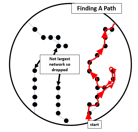
Using the networkx library, I can actually generate these paths quite easily! The output of this process gives me a path. Finally, I take the path and convert it into a series of steps that I can pass in to my motors. These steps I produce are the result of subtracting locations in the path with the prior location.
path =  [(12,5),(12,6),(13,6),(14,7),...] # coordinates
steps = [(0,1),(1,0),(1,1),...]           # differences
Results
And…viola! The path above is exactly what we needed. The motors are a bit slow, so here’s a time lapse of the etch a sketch drawing an elephant. This represents about 20 minutes of time in real life.
Not bad at all. Below are a few other examples. An additional note – my program resizes images which can end up stretching them a bit horizontally. This was done just for convenience to make sure all input pictures would fit on the screen. If there’s a specific picture you really wanted to draw, you wouldn’t need to do this. All of these run for several hours.
Batman
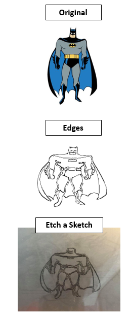
- image stretching makes batman look swole
- faces are hard
- etch looks more like a generalized superhero rather than batman (no clue where his “ears” went)
A Self Portrait
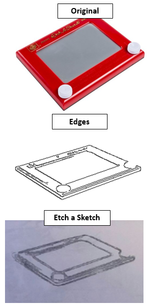
- right knob is hard for the edge detection to pick up
- the etching reproduces the edges, but the edges don’t look 3D
Low Library at Columbia
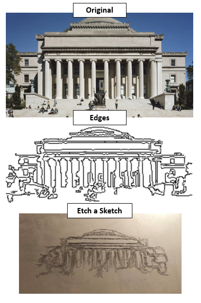
- this turned out way better than I thought it would
- edge detection struggles with sculptures (alma mater is unrecognizable)
- etching is a little bit fuzzy
Great Wave
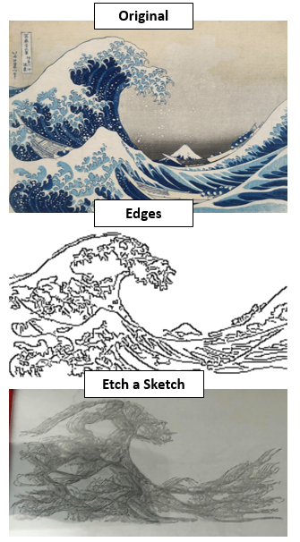
- I think this one is excellent
- Fuzziness of the etching works fine because it’s water
- Etch a sketch appears to have drifted rightword slightly – see mt. fuji is not perfectly lined up on every pass. Most likely due to drawing too close to left side of etch a sketch.
Further Work
I’m happy with how this turned out! I feel like I’ve accomplished the goals I had with this. There are several big areas of improvement remaining that I just want to mention here. Maybe I’ll revisit these at some point. My current plan is to draw a few of these on the screen at the same time, maybe freeze it, and then just put it on my wall as a little art piece.
The most glaring of these is the pathfinding. Doing depth first search with backtracking leads to insanely long paths. Finding the shortest path that hits all nodes in my network is a hard problem, but it lead to a huge reduction in draw times. There are approximations to problems like this out there and there are several tricks I could use to help (for example, maybe I only need to hit 90% of the pixels). The less time drawing, the less time for mechanical error to accumulate and results will be sharper.
The next issue is the edge detection. I didn’t want to spend much time on this on my first pass, but it’s clear that the drawings can only be as good as the edges going in. I tried a lot of images and found that often times the edges just weren’t really recognizable without seeing the original image. This is because I used a simple, general plug and play approach to edge detection. If I created my own version of this I could more carefully tune parameters to my specific use case.
Finally, better mounting for the motors would also help cut down on mechanical errors.
Other Stuff
Bugs
If you attempt to do something similar, keep an eye out for nasty mechanical bugs. When motors change directions, there can be a bit of “give” resulting in a deadzone. This is highly dependent on your own build. This took me FOREVER to diagnose. To fix it, I drew a series of grids to quantify exactly how many rotation units this deadzone was. I then added logic to my motor class to add extra rotation units when the direction was changing.